SOSA/VPX C-Frame Next Gen Evaluation Platform
Introduction
In specifying a VPX based system architecture, the backplane sits at the heart of the system and the topology is one of the fundamental building blocks of the design. The OpenVPX specification allows a high number of different backplane permutations. SOSA significantly reduces this be standardizing on a subset of board profiles, choosing the right configuration is still a challenge and the risks involved in getting it wrong can be costly. Whilst cabling solutions are available to manually configure uncommitted backplanes, these can be costly for high numbers of links and are not reliable for high-speed links such as 100G. The increasing market demand for higher bandwidth in OpenVPX systems driven by high-resolution multi-spectral sensor fusion, real-time edge-AI inference, and cognitive electronic warfare—has already begun to outpace 100G bandwidth. Comtel’s next generation of “C Frame” VPX development system is designed to address these issues.
Card Slots
- Slot count: 5-8
- Horizontal pitch: 1″ – 1.5″
- Forced air cooling
Card guide options for front cards
- Convection cooled cards (VITA 48.1)
- Conduction cooled cards (VITA48.2)
- AFT cards (VITA 48.5)
- Hybrid combinations
- VITA 46.10 card guides for RTMs
- Option for VITA 78 Space VPX (160mm & 220mm modules)
Backplane
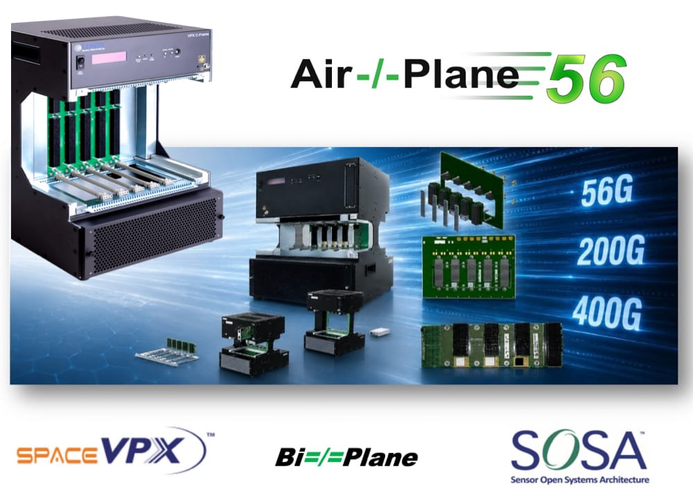
- Standard off the shelf split backplane Bi=/=Plane™
- Power and Utility Only (PUO) default*
- RTM connectors
- For 3U & 6U cards
- RT2 Multigig connectors
OR Committed
- Air-/-Plane56® technology for up to 56Gbps per Differential Pair
- IEEE 802.3cd 50GBASE-KR, 100GBASE-KR2, 200GBASE-KR4
- PCIe Gen 5
- Specify via configurator or contact sales.
- SOSA slot profiles
- RT3 MultiGig™ connectors
Cooling
- ΔT (inlet/outlet) based
- User programmable threshold management.
- VPX card remote controlled (with Chassis Manager card fitted)
- Front (Inlet) to Top (Exhaust)
Power
- Total consumption: up to 2000W
- Power input 230/110 VAC
- Total Power Output = 1600W
- 3V3@42A (3U only)
- 5V@34A
- P12V@133A
- 3V3(AUX)@5A
- P12V(AUX)@5A
- M12V(AUX)@1.25A
Integrated OLED Display
- Inlet/outlet air temperatures
- Fan speed / Control
- Supply voltages
- System power
System Management
- Built-in µC for power control and basic cooling
- VITA 46.11 compliant Chassis Manager card (option) with PigeonPoint ChMM700
- Ethernet (100BaseT)
- RS232 (DB9)
Chassis Dimensions
- Height: 460mm (3U version), 593mm (6U version)
- Width: 351mm
- Depth: 435mm
Environment
- 90-260VAC
- 0-35°C ambient temperature
- non-condensing
Field Replaceable Modules
- Card Guides
- Chassis Management Controller
- Signal backplane
- PSU
- Air Filter
For more informations – Please get in touch with our experts sa***@***********ne.com